

Station WN6F listening post
(click images to enlarge)
Last Update: 30 July 2005 (Be sure to see my 160 - 10 meter all-bander below!)
After doing battle with locally-generated EMI / RFI for nearly two decades, I decided to do something about it by trying out the so-called "shielded loop". This antenna's main advantage is that it packs a lot of low-angle directivity into a small package. This makes nulling out many urban noise sources easy while enjoying good medium to high-angle skywave reception. It also makes a great balanced rx antenna for very limited space environments.
(I apologize for the slightly disjointed appearance of these pages. I've made quite a few additions and removals and someday I'll get around to a total re-write...)


Small loop antennas range from .05 to .10 wavelength in circumference if you want to make use of bidirectional nulls and have some semblence of sensitivity. When you make the loop larger than .10 wavelength, you start to lose your low-angle nulls until you reach a point where the loop can no longer be considered "small". It is very much like a horizontal dipole mounted 1/4 wave high - the nulls however are broadside to the plane of the small loop. Do you have a 160m dipole up at 138 feet -- or an 80m dipole up at 70 feet?
(Right off the bat I should mention that what is described here is NOT a loop that shields itself from noise. We use rotation to null noise. By cutting a small gap in the shield at the top center of the loop, we actually destroy any "shielding", and force the outer skin of the braid to act as the antenna via the shield's outer common-mode. The gap separates the two "arms" of the loop, and at the bottom of the loop only a shield join is made to establish an electrically neutral point.
Prove it! Temporarily place a clamp-on common-mode ferrite cable choke on one of the loop arms and witness the signal deterioration. (If you place it on the feedline, it should have NO effect. If it does, you have an unbalanced situation (other than the coupling loop) which usually requires fixing the symetry of the loop construction.)
Inside the loop is an UNbalanced coupling loop, consisting of an unterminated center conductor. An unbalanced coupling loop is made by NOT shorting the center conductor to anything - leave it floating! An unbalanced coupling loop is ok, since the outer-skin braid antenna element is balanced. Signals couple from the outer skin element to the inner conductor loop via the gap. Most other shielded loop projects have balanced internal coupling loops, but I prefer the unbalanced type.
As long as everything outside is symetrical, the feedline to the loop should not become part of the antenna. You want to avoid this as much as possible - a quick test is to make sure that you have TWO nulls 180 degrees apart.
So why use coax? Because its convenient, easy to handle, has a larger surface area than a thin wire, and when wound in the way described, lets you turn a length of unbalanced coax into a balanced antenna without requiring the use of an external balun. There is no noise-shielding magic here now that we've cut a gap in it - electrical balance does all the work by using physical rotation of the antenna to cancel signals arriving broadside to the plane of the loop on the outer braid skin.
Also, Don't transmit NEAR these loops if they are connected to a receiver!
If you operate a small loop near a transmit antenna, you should make sure that you protect the front-end of your receiver from RF overload.
They are easy to build, and the only tools you'll need are wire cutters, and a knife. You can make them for yourself or friends in a matter of minutes. Part of my design goal was to use a minimum of easily available parts. (My gratitude to the original creators of gapped coax antennas) You won't need a well-stocked junkbox or any exceptional mechanical skills to build this antenna. The impedance of the cable is not critical, so use what you have lying around!
Winding the loops out of coax is very convenient and has five purposes:
The small wavelength outer-conductor loop (at 0.10 or smaller wavelength in circumference) provides the azimuthal low-angle bidirectional directivity with two deep nulls 180 degrees apart.
The gap in the braid at the top center of the loop acts as the feedpoint (don't attach or short anything here) to the center conductor and allows common-mode reception of signals on the outer skin of the loop braid to transition to the unbalanced center conductor. Rotating the loop nulls out the unwanted noise when the loop plane is broadside to the source.
The large amount of evenly distributed capacitance makes the loop somewhat resistant to unbalance and detuning from hand-body-earth object capacitance than more traditional balanced wire loops. This can be especially important indoors. Thus the broken "shield" serves as both the antenna element, and as an electrostatic shield. The use of the word "shield" in this application is kind of a misnomer - I would prefer "electrostatic balancer".
The larger outer conductor diameter of the braid increases the sensitivity of the loop over that of a very small-gauge wire.
The center-gapped loop forms it's own balun allowing the balanced braid antenna to couple to an unbalanced feedline.
HF loops built in this way are typically used for direct wave direction-finding. I'm more interested in using them as local noise-nullers to increase the signal-to-noise ratio. This helps make up for their lower sensitivity than more traditional long wire antennas.
A length of coax. Use the largest diameter you find practical. Note that some cable jackets can be very thin, so you might want to make some practice cuts on a discarded length first so you don't damage the braid. Actual cable impedance is not critical. I usually end up with 75-ohm RG-6 or 50 ohm RG-58 for convenience.
An antenna tuner can be used to tune the loop system to resonance. I use small T-type tuners. The loops are usable without a tuner, but I recommend one. When using low-cost tuners, check them for quality - dirty or burnt-out contacts can ruin your day. I've had many fail right out of the box and need immediate cleaning.
Optional: A 10 dB gain or more preamp can be used to help bring up the signal level. If your receiver has a preamp, and all it seems to do is bring up the local noise level along with the signals, you are in for a treat. With this directional antenna, the preamp finally becomes useful in amplifying the signals, and not the local noise. (Strictly speaking, preamps actually do both, but there's no point in applying a preamp to an S8 noise floor!) Lately I do just fine without preamps.
*** 6 July 2005 - WOW!! ***

I can barely tear myself away from the radio to write this up! Quick details: grabbed a 50-foot length of RG-6. Made a 40-foot single-turn gapped rectangular loop (a little bit larger than the image above) and used 10 feet of it for the feedline to the tuner. Loop is mounted indoors(!) at ground level next to a non-conductive wall with 8-foot vertical sides and 12-foot horizontal to fit room dimensions.
Gap is half-way up one vertical side at 4-feet and loop braid closure is up 4-feet on the other vertical side. Bottom half of loop is dressed along carpet edge. Loop is approximately .08 wavelength on 160m, .150 wavelength on 80m, (which is what I was mostly interested in) providing typical small-loop figure-8 low-angle directivity. I can't rotate it, but so far it is doing a great job nulling my neighbors television broadside to the loop on 160/80m. 40m and higher bands basically end up omnidirectional because they are much larger than .10 wavelength. 20m is not a small loop project anymore but a neat side-benefit.
Unreal! I just might be able to take my both my rotatable PVC monstrosity and twin-lead vertical out of the living room and keep my stealthy loop out of view. (They looked beautiful to me, but indoor antennas can scare your non-radio friends. Hi !) Forget that typical 20-foot coax loop limitation for 160 meters - instead of trying to resonate the loop with a series cap, you can resonate a much larger coax system. I am really excited about Top-Band 160m - for once I can clearly hear stations and even some big static-crashes! That natural noise never sounded so good! No preamplified desktop-loops here! You CAN go big even indoors! Just keep in mind that when you start to get much larger than .10 wavelength, you start to lose your nulls, so it's a tradeoff. (10 July: first 160m cw qso heard between Hawaii and Georgia - S2 strength)
Smaller version: try a 32-foot circumference (8-foot square loop) .05 wavelength on 160m, .12 wavelength on 80 still provides an ok null. 40 meters is beyond .10 so low-angle nulls are more oval. Nice .5 wave medium-sized loop for 20m. Place gap on center side, center top, or corners to play with elevation directivity on 20m or higher. Easier to hide indoors - perhaps use white coax.
160 meters optimized near .10 wavelength!
Create a 50-foot circumference loop (or quad or rectangle). I made this into a quad loop with 12.5 feet per side and mounted it vertically in the backyard. Outstanding! Until I can create a good way to rotate it, it is placed in fixed positions near some house walls depending on which noise I want to null. On any band higher than 160, the loop can no longer be classified as a small loop and I lose the bidirectional nulls. It makes a great improvement over my older series cap-tuned 20-foot coax loop. Lower leg of loop is about 6 inches above ground. As long as my loops have 180 degree bidirectional nulls, I can make relatively sure that the feedline is not the real antenna. It passes my simple choke-test where clamp-on chokes have no effect when placed on feedline, but attenuate signals when placed on the loop arms. Next project: put a rotator close to ground so I can rotate this thing with ease...
To assemble a real quick 80 / 40 meter loop, create a 16-foot circumference gapped loop and a 10 - 15 foot single coax feedline. For gap cutting instructions etc, see text below.
My best artistic attempts at drawing the schematics. (Click images to enlarge)
(Internet-Explorer users: IE has an option that automatically reduces the size of graphics. If the enlarged schematics look distorted even after clicking on them, be sure to view them full-size, typically with the F11 Key)

1) First, at one end of the coax, separate the braid and center conductor for a few inches. Make sure the center conductor does not short to the braid - perhaps insulate it by taping it. This small length of braid pigtail will later be wrapped around the exposed feedline braid.

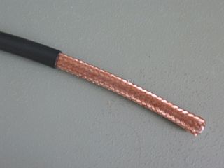
2) We need to create a 1-inch gap in the coax shield. Measure 8 feet from the previous step, and make a small cut mark on the coax. A half inch on either side of the mark, cut through the outer covering exposing the braid. Then cut the braid out to expose just the inner dielectric. Try not to cut into the inner dielectric as this will mechanically weaken the antenna when you eventually mount it. The photos show some exposed braid at the gap just for clarity, but my antennas just have a clean cut. Note that this is just a true gap, you do not short anything at the gap! (Make sure there aren't any fine strands of shield wire still connected across the gap after you cut it!) The actual gap size is not too critical - it only needs to be large enough that it won't short together when you form the loop. One-inch is fine.
KEY POINT: The gap allows common-mode reception of rf energy on the outer loop braid skin to transition to differential-mode currents on the inner braid skin, which is coupled to the center conductor. Thus the gap serves as the feedpoint to the center conductor. This is where the highest amount of signal occurs.

3) Measure another 8 feet from the center of the gap, and remove about 1 inch of the outer coax covering ONLY exposing the braid. Don't cut too deep or you'll damage the braid.

4) Take the braid-only pigtail end of the coax, and wrap it around the exposed feedline braid from the previous step. Solder or tightly wrap electrical tape around the joint. You may want to use a voltmeter to make sure that you haven't accidentally shorted the center conductor.
KEY POINT: This is the electrically neutral point of the loop where there should be no voltage. It is imperative that this point is directly opposite the top center braid-gap.
(NOTE: DON'T USE A TEE CONNECTOR HERE! It won't work properly. We need to wrap the braid-only end of the loop to the electrically neutral point on the exposed outer feedline braid exactly opposite the open gap to maintain electrical balance.)
You now have a highly directional low-angle 80 / 40 meter loop (almost omni for skywave angles) and the rest is a small length of feedline that goes to the input of your receiver or tuner. For 160m, you'll want to enlarge the loop circumference to at least 32 or 54 feet, or perhaps add a preamp. Unlike the photo, I now prefer T-type tuners that have large parallel inductance.


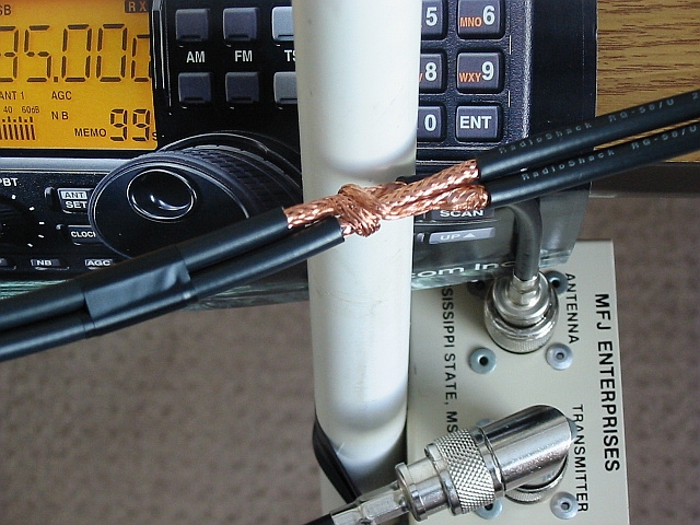
Note: Here is a very small loop for overall visual reference.
Note that when we cut loops for .10 wavelength, they will also perform well at half their frequency as a .05 wavelength, (ie a loop cut for 80 but trying to operate it at 160) although sensitivity will be down somewhat. The positive tradeoff is that the nulls will be VERY deep at .05 wavelength for those really stubborn noise situations.
My apologies go to earlier readers of these pages. I incorrectly assumed that since we are using coax as antenna elements, that they would be subject to a cable's velocity factor. The common-mode outer braid skin is not subject to the velocity factors we normally apply to the inner differential-mode. (The effect of the cover has proven to be negligible for such small lengths in my experiments)
The standard formula for calculating the loop circumference for the highest frequency of interest at 1/10th wavelength without any VF, is:
Generally, anything between .05 and .10 wavelength will work with acceptable efficiency and provide good nulls, (for small loops that is) and .08 wavelength is ideal. The value of 1005 is the classic textbook value for quad-loops, but you may want to research this value and see if 1032 or higher is more suitable. The next time I build my coax loops I think I'll try 1032 for 160-40 meters and 1050 for 20 meters and higher. (This is easy for me to remember if I just transpose the last two digits of the "textbook" value.) It all really depends upon wire diameter / wavelength, but it doesn't seem to critical in this rx-only application. Maybe this is why I could still obtain pretty decent nulls when my loops started to exceed .10 wavelength when using the textbook value!
TUNING NOTES
This formula should get you in the ballpark, although if you can't get a definite peak with your tuner, try using a more advanced tuner, change the loop perimeter, swap the input/output of the tuner, use lower capacitance cable, or change the feedline length before reaching the tuner. I'm not trying to resonate the loop itself -- I'm just trying to optimize the sensitivity of the whole system by presenting an impedance the tuner / receiver can handle - even if it is somewhat reactive.
I have found that making a loop larger in area (as close to .10 w/l circumference as you can get) can overcome impedances that are not ideal. A large non-resonant reactive loop is more efficient than a paper-clip loop tuned to present an exact 50 ohm resistive match to the receiver! This is why I don't get too hung up on loop inductance calculations only to find that a series matching capacitor in the loop results in a loop much smaller than .10 wavelength.
Fortunately it is easy to make a pre-cut loop shorter if you need to. Let's cut off two feet from the existing loop circumference as an example:
Unwrap the braid-only lead from around the exposed feedline braid. Cut away a foot from this arm of the loop and create another braid-only end.
Measure a foot from the center of the old exposed braid, and cut a new 1-inch exposure of braid.
Wrap the new braid lead around the new exposed braid section and re-shape the antenna into the smaller shape. Tape up or heat-shrink the older exposed braid section.
Try to be as accurate as possible and strive for balance when re-sizing the loop. Balance is important!
These loops perform well very close to ground. In fact, if you mount the antenna much higher than .20 wavelength, no appreciable difference is made to low-angle reception, and for the most part you start to attenuate your high-angle reception. As you approach 1/2 wavelength high, you start to get a REAL cloud receptor. So for me, I'll just keep my small vertical loops low. Mounting these small loops high away from noise kind of negates the purpose of noise nulls anyway so you might as well use a "real" antenna. hi.

On the left is a 40 meter .10 wavelength circumference loop mounted 1/4 wave high.
On the right is the same loop mounted up at 1/2 wavelength above ground.
I'm not sure these elevated heights are worth the effort - especially not at 1/2 wavelength elevation! All you'll accomplish at these heights is possibly increase the strength of direct-wave locals. If it acts like a noisy vertical and you've lost low-angle bidirectional directivity, your loop is unbalanced and the feedline has become part of the antenna! Check for mechanical / electrical symetry.
You can create the loop with any shape you want, but circles are best; squares and diamonds do nearly as well. Triangles, and extreme rectangles don't do as well, but don't let that stop you - even irregular shapes seem to work, just not as well. The key is to enclose as much area as possible. A large single turn triangle may contain more area than a small circle. For mounting, any sort of cross-brace should work, but I've also placed them on the back of non-metallic doors, non-conducting room dividers, hung them from ceilings, used camera tripods, etc.
You should be able to null noise (if the antenna is .10 wavelength or less) in two positions by rotating the loop at least 180 degrees. If you can obtain a null in only one position, it is likely that the loop has become unbalanced and the feedline has become part of the antenna - which is what we don't want. Check your construction techniques to make sure that everything is symetrical. If everything seems ok and you are indoors, there may be a massively hidden object in the walls swamping the balance. If everything check out ok, but are still bothered by noise, check for common-mode cable noise ingress -- check your grounds or apply a choke to the feedline or the feedline of other antennas. Your local noise floor may be so low with the loop that you might be able to detect a common-mode noise problem that was covered up before!
(If you are experimenting with these loops and suddenly discover some new noises on your other antennas, disconnect the loop and see if the noise goes away. If it does, you might have a common-mode problem that needs grounding and/or choking.
Quick tuner tips: Once the band is open with a TEE-type tuner, (two caps and an inductor) you will probably have to be more methodical to find the peak. They are easy to miss unless you just happen to chance upon it. It's a pain to do, but here's a typical initial tuning session for a new loop with a tee-type tuner:
Start with max inductance and both caps fully meshed.
Rotate the ANTENNA cap through its range. If no peak heard, move it back to start.
Move the RECEIVER cap up by one notch.
Rotate the ANTENNA cap through it's range. If no peak heard, move it back to start.
Move the RECEIVER cap up to the second notch.
Rotate the ANTENNA cap through it's range. Continue this procedure of moving the RECEIVER cap slightly and then rotating the ANTENNA cap through the whole range.
When you have exhausted all positions of both antenna and receiver caps and have found no peak, change the INDUCTOR by one notch.
Methodically move the receiver and antenna caps again as indicated above until you find a peak. If not, move the inductor a notch and try again.
Once you have found a peak, be sure to try one or more inductor changes and receiver/antenna cap swings to see if you are very close to an even better peak! Also remember that if you tune off frequency by very much you will probably want to do a touch-up on the peak with one of the caps. This is easy to forget when you try a loop for the first time. The off frequency tuning touch-ups aren't super-critical -- I might repeak when I go from one band edge to the other. On 160 however, you'll want to re-peak often.
Note to experimenters: I've spent a lot of wasted time trying to tune and evaluate loops when the bands aren't open. Save yourself some time and frustration and merely wait for the skywave signals. Forget trying to evaluate them on direct-wave locals.
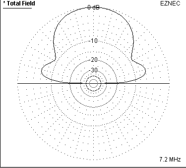
The horizontal directivity pattern is a bidirectional figure-8 pattern at low angles, with maximum gain in the plane of the loop, and the nulls are broadside to it. It is just the opposite of an ordinary dipole. The loop seems progressively more omnidirectional to medium and high skywave angles and you may even detect the slight overhead oval pattern.
You don't have to have the loop perfectly vertical, use whatever angle you need to null the local noise or storm-related static crashes - skywave signals will still be heard well. In one case, I have a noisemaker downstairs, so I had to rotate and tilt the loop at about 45 degrees to null it - it didn't attenuate the desired band signals at all. At times I've been able to track a storm all night and reduce the static crashes, and then sometimes not depending upon how localized the storm is.
You might notice that even though you've nulled out the noise, signal levels on a tuned loop seem to be about 2-to-4 S-units down from a standard 1/2-wave dipole mounted up at least a wavelength above ground. This is normal for a small loop given its short wavelength. You can compensate with a preamp, but you might find that with the noise level so low, you'll do just fine with only a tuner. If your normal antenna isn't mounted up at least a half-wavelength, the comparative loss might be even less! (With my 16 and 32-foot circumference loops, I consistently get 10 - 20 over S9 signals much of the time with S1-S2 noise floors - not counting static crashes of course)
Note: many modern radios that have built-in selectable preamps might have much lower sensitivity with their preamps off than other radios that don't have any preamps at all. This is a good design feature. Accordingly, with radios that have selectable preamps, it is likely you'll want to run with at least the first preamp turned ON.
The important point to remember is that your local noise floor will be so much lower than your old noisy antenna that it more than makes up for brute signal strength. What's better: a large antenna on 80 meters that consistently reads an S8 man-made noise floor with +10 over 9 signals OR a small loop with an S1 noise floor and signals that only go up to S9? I'll take the small loop with it's 54 dB signal-to-noise ratio over the larger wire antenna with only 16 dB SNR any day. (assuming each S-unit represents a 6dB change) I can't stand listener-fatigue and for me, DSP noise reduction is an oxy-moron.
Make sure your connections are snug. If you lose the ground, you'll end up with a random-wire because you've lost the electrical balance. I mention this because as you insert or remove the connector from the tuner or receiver, when only the center-conductor is making a connection, you'll hear noise or signal level come up a bit. Unfortunately, you will have lost all the directivity that this antenna provides. Keep those connections tight.
A caution about crimped PL-259 connectors: sometimes the crimp is so tight that when you screw them fully into the chassis jacks, they don't actually make good contact with the chassis-connector center conductor. A VERY GENTLE squeeze with a pair of pliers on the center-conductor pin will help ensure good physical contact. I've run into this problem a lot with cheaper cables and sometimes it is not immediately apparent because you can still receive signals (poorly) due to capacitive coupling of the center pins.
Another drawback of cheaper connectors is that when you mate the dielectrics of the cable plug and chassis jack together, they sometimes don't allow the shells to make contact, especially if the "teeth" are short. You might only have a very poor shell-to-chassis connection via the rubbing of the cable's screw ring to the shell. Use quality connectors or your loop will complain!

To turn a large loop into something more manageable size-wise, try a parallel-wound TWO-TURN loop to reduce the loop diameter in half yet effectively double the braid conductor diameter. Each turn should have a 1-inch gap at the top of the turns, and at the bottom of the turns you attach the exposed braids and braid pigtail together.
Turn spacing: you might want to put a coax-diameter's width of space between the two turns. I did this by winding one turn on the front of the mast and the other turn on the back.
(Click on any image to enlarge)

For example, my 80 /40 meter single-turn diamond loop has a 16-foot circumference with an approximate 4.5 foot diameter.
I turned it into a two-turn loop by starting with a new 16-foot length of coax, and depth-winding a second continuous turn around a 2-foot circular diameter instead of a square 4-foot diameter. At the top of the loop are my two turns with the 1-inch gaps at the center. At the bottom output of the loop I made sure the exposed braids and braid pigtail are connected together. From this point, I ran about 10 feet of feedline before it connects to the tuner / receiver.
Try to make all your measurements, cuts, and braid connections as symetrical as possible. Making the loop balanced is key to good noise rejection.
The results of this two-turn loop are great! Signal output levels between my larger single and smaller double-turn parallel loops seem about the same. It points out the relationship between enclosed area vs. conductor diameter. Obvious lesson: used the larger diameter coax if you can.
If you bypass the tuner, you might be able to use a loop cut for 80 or 160 meters in an untuned mode for casual MF BCB and LF reception. It is handy to null out the local broadcasters.
When I bypassed the tuner, I finally heard low-frequency CW beacons. So there IS life down there! For serious use, I'd definitely recommend specialized antennas for these bands, but at least an untuned loop might whet your appetite to go "lowdown".
I am indebted to all the Amateur Radio operators, SWL's, BCB DX'ers, VLF'ers and other experimenters that provide me with information and encouragement with this project. They participate in the Yahoo!® Loop group and also on the rec.radio.amateur.antenna newsgroup. All errors and misinterpretations belong to me however ...
If you're interested in loops, whether they be shielded, unshielded, magnetic, loopsticks, etc, you can find a great discussion forum for loop antennas on Yahoo!® by clicking here.
Be sure to visit the K7ZB site with his pics and nice build of this loop, along with other interesting antenna solutions.
More LINKS to my other receive-only small loop research:

since 1 June 2003
© 2002-2005 www.greertech.com