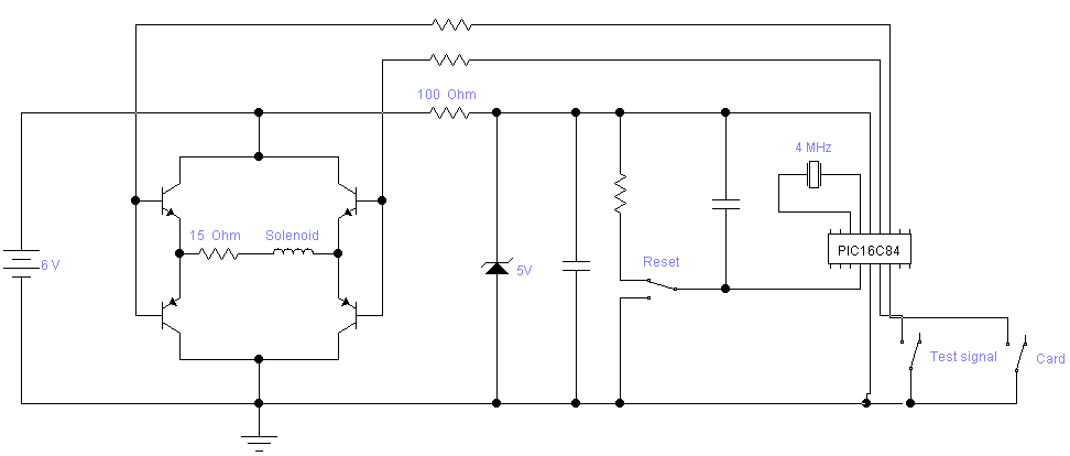
Figure 1: Schematic for the emulator
Magnetic stripe cards are used for many purposes today, from credit cards to security passes and room keys. This article doesn't intend to explain how to read the contents of a magnetic stripe card. If you're interested in that, see for example Magnetic stripe reader/writer. This article covers emulating magnetic stripe cards for academic purposes such as brute-forcing for an authorized card for a door lock. I have only emulated track 2 of the card, but there's no real obstacles to extending this to track 1 and 3 as well.
To be able to understand this article fully and build the emulator described, you will need knowledge on PIC programming, some electronics construction skill as well as knowing the basics of magnetic stripe card encoding.
The hardware consists of a microprocessor, a PIC16C84, generating pulses controlling the magnetic flux in a solenoid, and some switches and capacitors to control the PIC as well as some transistors to amplify the current to drive the solenoid, see figure 1.

The solenoid will transfer the pulses from the microprocessor to the magnetic head in the card reader. It needs to be put into the right position to be read. The easiest way to accomplish this is to cut a hole into any old real magnetic stripe card you might have around, and place the solenoid there. According to the iso standard for magnetic stripe cards, track 2 is the area between 0.353" and 0.463" from the edge of the card. You don't need to cut a hole all the way along the card since the magnetic head in the reader is only some quarter of an inch long.
The solenoid core can be made from thin magnetic sheet-metal. The card itself is about 0.7mm thick. The solenoid core should preferably be slightly thinner so there's space for two layers of copper wire without the solenoid getting much thicker than the rest of the card. For this test I used a 0.5mm x 3mm x 45mm piece of steel, cut from a can, wrapping about 1m of 0.1mm copper wire onto the ends of that (see figure 2).

The software (see figure 3) contains two functions: To generate a series of 0 bits as a test pattern and to generate the data for a valid card. The desired function is selected by putting a low level on pin RB0 for test or RB1 for card. The output waveform is available on pin RB7, and in inverted form on pin RB6. When no function is selected, both pins are pulled high by the internal weak pull-ups.
The data for the stripe of the card is stored inside the PIC. The code is prepared for adding more cards, selected using pins RB2 and RB3. Feel free to use the code as a base for your own magnetic card projects, but do give proper credits. If you make an improved version I would also appreciate a copy of the new source code.
	list p=16c84

	include "p16c84.inc"


count	equ	0x0c
bit	equ	0x0d
i	equ	0x0e
d	equ	0x0f
parity	equ	0x10
cardsel	equ	0x11


	errorlevel -302
	; Start at the reset vector
	org	0x000
start
	banksel OPTION_REG
	bcf	OPTION_REG, NOT_RBPU
	banksel PORTB

retmain
	banksel	OPTION_REG
	bsf	PORTB, 6
	bsf	PORTB, 7
	banksel PORTB
main
	btfss	PORTB, 0
	goto	zerobits
	btfss	PORTB, 1
	goto	card1
	btfss	PORTB, 2
	goto	card2
	btfss	PORTB, 3
	goto	card3
	goto	main


card1
	movlw	0
	movwf	cardsel
	goto	testpattern

card2
	movlw	p2-p1
	movwf	cardsel
	goto	testpattern

card3
	movlw	p3-p1
	movwf	cardsel
	goto	testpattern


; ---------------------------------------------------------------------------------
; -  Send 0-bits
; ---------------------------------------------------------------------------------

zerobits
	banksel	OPTION_REG
	bcf	PORTB, 6
	bcf	PORTB, 7
	banksel PORTB
	bsf	PORTB, 6
	bcf	PORTB, 7
zb_loop
	call	sendbit0
	btfss	PORTB, 0
	goto	zb_loop
	goto	retmain

; ---------------------------------------------------------------------------------
; -  Test pattern
; ---------------------------------------------------------------------------------

testpattern
	banksel	OPTION_REG
	bcf	PORTB, 6
	bcf	PORTB, 7
	banksel PORTB
	bsf	PORTB, 6
	bcf	PORTB, 7
	movlw	0x10
	movwf	i
tp_init					; Send 16 0-bits
	call	sendbit0
	decfsz	i, f
	goto	tp_init

	movf	cardsel, w
	movwf	i
	clrf	parity
tp_loop
	movf	i, w
	call	getpattern
	andlw	0xff
	btfsc	STATUS, Z
	goto	tp_endloop
	andlw	0x0f
	movwf	d
	xorwf	parity, f

	bsf	parity, 7
	movlw	0x04
	movwf	bit
tp_bit_loop
	btfsc	d, 0
	call	sendbit1
	btfss	d, 0
	call	sendbit0
	movlw	0x80
	btfsc	d, 0
	xorwf	parity, f
	rrf	d, f
	decfsz	bit, f
	goto	tp_bit_loop

	btfsc	parity, 7
	call	sendbit1
	btfss	parity, 7
	call	sendbit0

	incf	i, f
	goto	tp_loop

tp_endloop
	movlw	0x10
	movwf	i
tp_deinit				; Send 16 0-bits
	call	sendbit0
	decfsz	i, f
	goto	tp_deinit


waitforreturn0
	clrf	i
waitforreturn
	btfss	PORTB, 3
	goto	waitforreturn0
	btfss	PORTB, 2
	goto	waitforreturn0
	btfss	PORTB, 1
	goto	waitforreturn0
	decfsz	i, f
	goto	waitforreturn
	goto	retmain


; ---------------------------------------------------------------------------------
; -  Send 1-bit
; ---------------------------------------------------------------------------------

sendbit1
	clrf	count
	call	delay
	movlw	0xc0
	xorwf	PORTB, f
	clrf	count
	call	delay
	xorwf	PORTB, f
	return


; ---------------------------------------------------------------------------------
; -  Send 0-bit
; ---------------------------------------------------------------------------------

sendbit0
	clrf	count
	call	delay
	call	delay
	movlw	0xc0
	xorwf	PORTB, f
	return


; ---------------------------------------------------------------------------------
; -  Delay count * 8 us
; ---------------------------------------------------------------------------------

delay	nop
	nop
	nop
	nop
	nop
	decfsz	count, f
	goto	delay
	return


	org	0x300
getpattern
	bsf	PCLATH, 0
	bsf	PCLATH, 1
	addwf	PCL, f
p1	dt	";199760057?6", 0
p2	dt	"", 0
p3	dt	"", 0


	__config _CP_OFF & _PWRTE_OFF & _WDT_OFF & _XT_OSC
	end
Figure 3: Source code for PIC