26 April 2002
A Short, Driven, Foucault Pendulum
by John
Dooley
Professor of Physics, Millersville University
Editor's Note: Prof. Dooley
will be making a presentation about this pendulum project at the upcoming
SAS
Annual Convention.
The inspiration for this project was three-fold:
|
Image updated every 9 seconds. Reload to see current image |

1) The new science building at Millersville has a three story stairwell which cried out for a Foucault pendulum, but there was no money available for the standard monumental version (cost between $50,000 and $100,000).
2) Dr. Nolan found an article by Richard Crane showing that a short driven Foucault pendulum could be built. The reference is:
A Foucault Pendulum "Wall Clock" by Richard H. Crane American Journal of Physics 63, (1) 33-39 (1995).
3) Meron Wollie showed that we can parametrically drive a short pendulum with equipment readily at hand
|
Click individual images to enlarge |


The rotation of the plane of oscillation of the Foucault pendulum is the most immediate and convincing evidence that the earth turns on its axis. The figure shows the 1 meter driven Foucault pendulum in operation in the Physics laboratories of Millersville University. The pendulum oscillates with a period of 2.1 seconds. The figure is updated every 9 seconds. To see the latest figure, click on the refresh (or reload) button of your browser. (Some internet services cache the page that you view and refuse to truly refresh. If this happens, open Netscape or Explorer and view the real time image in one of those browsers.)
A live sequence of 5 sequential images of the pendulum, (9 seconds apart) is shown on the left. This nice development was made by our technician, Shawn Reinfried. We were encouraged to try it by Doug Bowman, a workshop participant who found a way to put multiple images of his pendulum on the web.
Because the period is not an even fraction of the update time period, each image will show the pendulum in a slightly different position. A few refresh cycles will give a sense of how the pendulum is swinging. At Millersville's latitude of about 40 degrees North, the pendulum should take about 36 hours to precess through an entire 360 degrees, meaning that it should precess about 10 degrees per hour.
The rate of rotation of our pendulum is not constant, because of imperfections in the pivot point. Thus, the times marked on the scale below the pendulum must be regarded as our wish rather than our achievement.
For a minute-by-minute record of another kind of real-time earthly motion, check out the MU Earth Science Seismograph page. The March 26, 2002 earthquake in Afganistan is recorded in the archive section of that site.
Construction Details
The aim is to build a working Foucault pendulum (to demonstrate the rotation of the earth on its axis) using materials from a modern American mall. The pendulum, mounted on a 4 foot ladder, is shown at the right.
The two main engineering problems are:
First, replacing the energy lost (mostly due to wind resistance) so that the pendulum continues to swing without "dying down." If this is not done, for a pendulum of ordinary size, the swing comes to a stop before the earth has had time to rotate significantly, and the evidence for the rotation is lost.
Second, ensuring that the pendulum will swing with equal ease in all directions. Without special care a pendulum has a preferred direction of swing. When its plane of oscillation arrives at a preferred direction, the pendulum tends to stay there, and evidence for the earth's rotation is lost.
The Pendulum Pivot
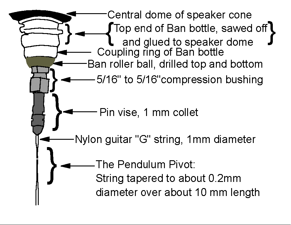
The pivot is the most delicate component of the pendulum. It must have cylindrical symmetry. That is, it must look the same from every direction, as it hangs vertically. The method of creating a symmetric pivot here is to carve it from the existing nylon guitar string.
The diameter of the guitar string is about 1 mm. The string is thinned, over a length of about 1 cm, to a diameter of about 0.3 mm, or less. This can be done with sandpaper, stroking down, and turning the string about the vertical axis after each stroke. In practice the string tends to turn to a ribbon instead of a cylinder, but the procedure has yielded successful pivots for this pendulum.
|
Click image to enlarge |

The method used currently involves more equipment, but reduces preparation time from days to minutes. A sketch is shown at the right. The string hangs from the chuck of a drill press, tensioned with a weight of about 200 grams at the bottom. A Dremel tool with a grinding cutter in place is mounted on a translating stage so that the cutter moves sideways to touch the string, just below the chuck jaws.
The drill press chuck is rotated at about 1 revolution per minute while the cutter is pressed a little closer with each revolution. To make the drill press rotate that slowly, the motor from a barbecue rotisserie is fastened to the ordinary drive shaft, with a piece of car radiator hose. The rotisserie motor is clamped to the lid of the drill press pulley chamber.
The cutter makes a quarter-moon shaped groove around the string. When the thinnest part is about 0.3mm in diameter, the Dremel is pulled away. The drill press chuck is loosened and the string is lowered about 2 mm. The process is repeated, so that the string has the appearance of a string of beads, about 1cm long.
The finished guitar string is mounted in the pin vise. The pin vise collet is 1 to 2 mm above the top most groove of the pivot. This insures that the string flexes in the grooved section, and not at the pin vise collet. The pin vise collet is not cylindrically symmetric, and will create preferred directions, if the pivot point is at the collet.
The Pendulum Bob
The bob shown at the Millersville web site is made from PVC pipe cap, with mass of about 100 gram. The pipe cap is threaded onto a hollow threaded rod used in lamp hardware. The pitch the threads is one thread per mm. The pipe cap can easily be moved vertically a distance as small as 0.1mm. This sensitivity is needed to match the natural pendulum frequency to the driver frequency.
The pendulum resonance is narrow, perhaps 0.0005 Hz for a frequency of 0.5 Hz. The length needs to be adjusted with a precision of a part in 10,000.
|
Click image to enlarge |
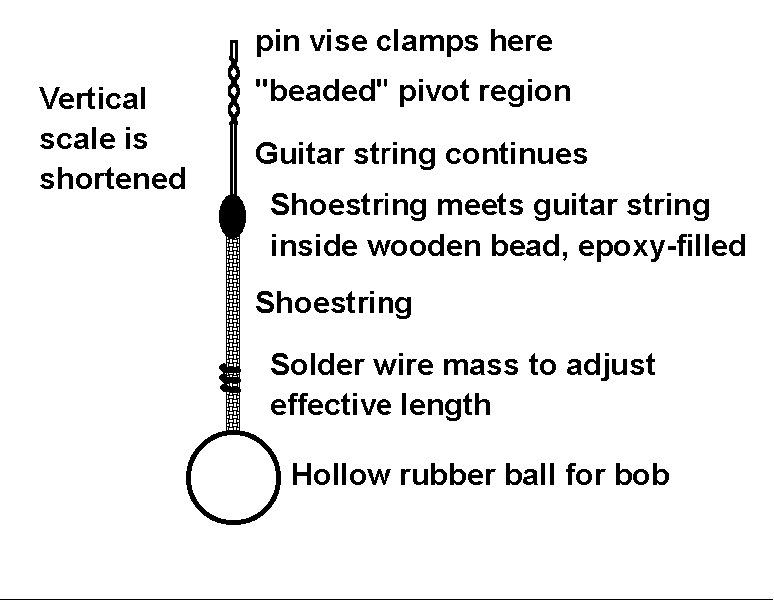
The bob described here is simple. The effective length of the pendulum is adjusted by moving small weights along the string. The bob is attached to the pivot by a cylindrical shoe string, made for hiking boots. The shoe string is epoxied to the bottom end of the guitar string, with care taken to maintain cylindrical symmetry.
The bob itself is a hollow rubber ball, sold for playing the game of racquetball. The low mass and large surface area of the bob makes it lose energy more quickly than a heavy bob, but the pumping driver provides enough to replace the loss. The high energy loss broadens the pendulum resonance, making the adjustment for length somewhat more forgiving.
The ball has a small hole cut in the top and a larger hole in the bottom. The shoe string is threaded through the top and then the bottom. A knot is tied in the string and pushed back through the bottom hole. The knot holds agains the inside top of the ball, so that the top of the ball is 1 meter from the pivot. (The design assumes a 1 second square wave driver.)
The effective length of the pendulum is adjusted with a 1cm length of solder wire, 1mm in diameter. The wire is spiral wrapped tightly around the shoe string. It is slide up and down to adjust the effective length of the pendulum.
The process of matching the natural frequency of the pendulum to the frequency of the square wave requires adjusting the length of the pendulum, much as old fashioned grandfather clocks were regulated (See below).
Pumping a Home-Made Foucault Pendulum
|
Click image to enlarge |

The speaker is driven up and down with power supplied by a 9 volt, 800mA "power adapter" Radio Shack number 273-1770. The relay, Radio Shack number 275-248A is rated for a 12 volt coil, with 10 Amp contacts. The speaker draws less than 1 Amp, but lower rated contacts burned after about a month of operation.
A 1 Hz square wave switches the relay on and off, and this drives the speaker up and down. See here for the square wave generator. The 10 Ohm resistor limits the current to the loudspeaker. In addition, in combination with the 2200 microFarad capacitor, it creates a low pass filter that eliminates a popping sound in the speaker, from the edges on the square wave.
Coupling the Pendulum Pivot to the Driving Loudspeaker
|
Click image to enlarge |
The coupling mechanism is designed to be flexible. It allows easy disassembly at two separate points.
Building it begins with a classic Ban RollOn deodorant bottle. Remove the Cap and saw the top off the bottle, just below the point where the threaded part meets the main part of the bottle. If it is still in place, pop the ball out of its retaining ring.
The loudspeaker used is a 6 1/6 inch 40 watt long-throw woofer, Radio Shack part number 40-1033. At the center of the speaker cone is a solid dome. Roughen this dome with sand paper.
With 5 minute epoxy, glue the sawed-off top of the ban bottle to the center dome of the speaker.
|
Click image to enlarge |

While the epoxy is setting, drill a hole through the ball from the deodorant bottle. The ball is made from two half-spheres joined together. The joint forms the midline of the ball. Drill the holes so that they do not cut through the midline. It is hard to drill a hole larger than about 1/4 inch. The hole needs to be opened up to about 1 cm in diameter. This is most easily done with a "nippy cutter" wire cutter, Radio Shack part number 64-1833D. The exact size is adjusted to fit the bushing, see below.
The bushing is a standard brass 5/16" compression union. The upper compression ring is removed, and (with the upper nut still off) the upper part of the bushing is threaded into the lower hole of the deodorant ball. The upper hole in the deodorant ball is made large enough to pass the bushing nut. The upper nut is passed through the upper hole, and screwed back on the upper bushing threads. This will fasten the bushing to the bottom hole of the ball.
The bushing holds the shank of a pin vise. It may be necessary to wrap one layer of electrical tape around the shank in order to have the compression ring grip tightly. The pin vise chuck should hold a 1 mm pin. A dual pin vise (which can be sawed in half to get two working vises is listed at about $10 at www.metricsupply.com.
The pin vise holds the guitar string above the pivot.
Square Wave Generator
The driver must pump the pendulum within a fraction of a percent of the pendulum natural frequency, for a period of months. To maintain this constant a driving frequency, in practice, the square wave must be controlled by a crystal clock. The drivers for an ordinary LED display clock are sufficient to switch the relay, but it is tricky, and a little dangerous to gain access to that square wave.
In the circuit shown above a quartz controlled electronic metronome (called QwikTime) supplies pulses every second.
|
Click image to enlarge |

The metronome will run for several days on its 9 volt battery. The battery is replaced by a second Radio Shack 9V power supply. The supply is not regulated and in fact produces about 11.5V at low current. A 60 Ohm resistor in series with the positive lead of the power supply drops the voltage to a safe 9 V for the metronome. The circuit for the metronome is show at the right. To replace the battery, a new battery connector is used. This connector will couple to the connector already in the metronome. To make it work right, the new connector has its red lead connected to the negative side of the power supply and the black lead connected to the positive side, as shown. Do it wrong, and the metronome will probably burn out.
The pulse each second from the metronome is used with a 555 integrated circuit to produce a square wave with a 1 second period. In this configuration, the 555 is said to operate as a one-shot multivibrator. It works like this:
The pulse triggers a transition to high voltage out in the 555 timer chip. After a time (0.5 second) determined by the time constant of the RC part of the circuit, the 555 returns to zero output and awaits the next trigger pulse. The circuit to make the 555 runs as an triggered one-shot multivibrator is discussed on pages 227-228 in Principles of Electronic Instrumentation, third edition, by Diefenderfer and Holton from Saunders Publishing.
|
Click image to enlarge |

In the figure, pin 4 is connected to pin 8 (the positive power supply connection), and pin 5 is capacitively coupled to ground, following Diefenderfer's instructions "for stable operation."
In the circuit, the 555 trigger input (TRGGR) is held at 9V with the the 4700 Ohm resistor. When this is the situation, the output voltage (pin 3) is zero. Once each second, the metronome pulse is brought in on two wires, connected across the 4700 resistor so that the pulse drives pin 2 towards ground. Having a separate power supply for the metronome makes this easy to do. The purpose of the 0.1 microfarad capacitor on pin 2is to stretch the short metronome pulse and give the 555 time to respond to it.
When the 555 detects the negative going trigger, it raises the output from 0 to 9 V. The 10 KiloOhm variable resistor is adjusted so that the time constant (with the 47 microFarad capacitor) is approximately half a second. With this resistance correctly set, the 555 output returns to zero after 0.5 second, and awaits the next trigger.
The effect is to produce a square wave at the output with a 1 second period. This square wave is sent to the relay coil, and the relay in turn swtiches the power to the speaker, in the form of a 1 second square wave.
The metronome can tick as slow as 40 times per minute and as fast as 200 per minute. This means that the circuit can match the natural frequency of any member of a family of pendulums whose lengths vary from 1.2 meters to .5 meters. (Lore has it that shorter pendums are harder to get working.)
Matching the Pendulum Frequency to the Driver Frequency
Assume for concreteness that the driver is a 1 Hz square wave. When pumping efficiently, the driver will pull up on the string each time that the bob passes through its lowest point. This means that we want the natural frequency of the pendulum to be 0.5 Hz. (If we think of the clicking relay as sounding like the "tick-tock" of a grandfather clock, then from "tick" to "tick" is 2 seconds. From "tick" to "tock" is 1 second.)
The pendulum resonance is narrow, perhaps 0.0005 Hz for a frequency of 0.5 Hz. The length needs to be adjusted with a precision of a part in 10,000. When the pendulum length is 1 meter, the frequency is very close to 0.5 Hz.
Referring to the figure, we start with the distance from the top of the ball to the middle of the pivot region set at 1 meter. Because the ball is about 5cm in diameter, the effective length of the pendulum is greater than 1 meter.
To find the resonance we need to shorten the effective length. This is done with a length of solder wrapped and pinched around the shoestring. (The length of the shoestring is about 1/2 meter, and the length of the guitar string is also about 1/2 meter.) The solder is 1 mm diameter, and about 4cm long.
As the solder is placed higher and higher on the shoestring, the effective length of the pendulum becomes shorter and shorter. Here is the recipe for deciding when the length is getting close to the correct length:
Pull the bob back about 10 cm and watch the speaker moving up and down. When the speaker coil drops down, release the bob. This timing will cause the speaker to pull up as the bob approaches its low point.
With the string too long, the period of the pendulum is too long; the pendulum takes too long to get through one cycle. As several cycles go by, the speaker will pull up too early, before the bob reaches the lowest point. Eventually, the speaker will be pulling up when the bob is actually at its highest point.
This progression is the sign that the string is too long. The solder wire needs to be moved up. Move it up about 1cm and try again. If the solder wire is moved up too far, then the speaker will pull up too late, after the ball has passed its low point.
It turns out that the best setting has the speaker pull up slightly before the ball reaches the lowest point. This means that the driver frequency is slightly above the natural frequency of the pendulum, but is close enough to pump in the required energy. The reason for this choice is a little esoteric:
The pendulum frequency depends slightly on the amplitude (maximum displacement) of the swing. At large amplitude, the frequency is a little lower. This effect leads to the conclusion that the pendulum is more stable if it is driven slightly above the natural frequency. An example helps show why.
Suppose that the temperature of the room goes up and the length of the guitar string increases. The pendulum frequency goes down and the speaker pumps in less energy. This causes the amplitude to decrease. But that causes a slight increase in natural frequency, so the speaker is once again close to the natural frequency.
These competing effects tend to keep the amplitude of the pendulum constant, provided that the driver is slightly above the natural frequency.
For a more thorough discussion
of the short, driven, Foucault Pendulum, and live snapshots of its motion,
visit the Millersville
University Physics website. ![]()